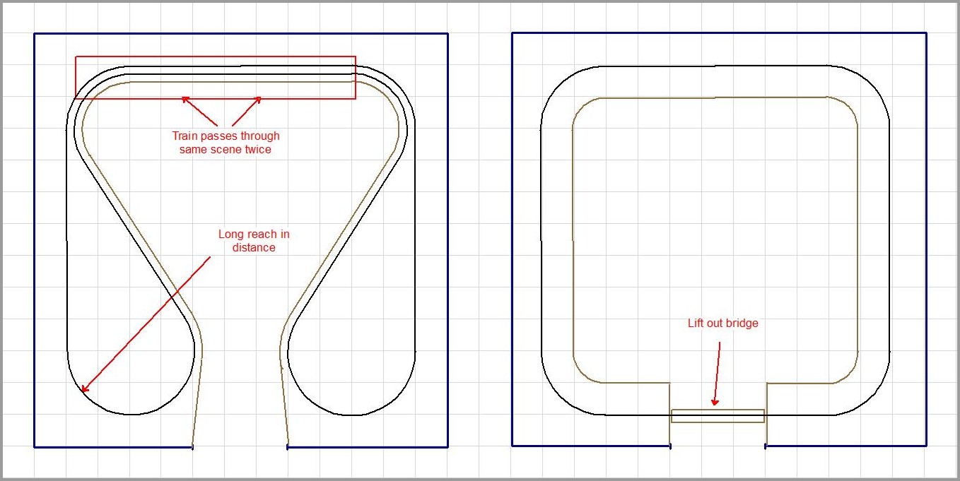
Those of us who want a continuous run design typically have two options. Let’s talk about how, when you weigh the pros and cons, the choice becomes obvious. The issue is, how do you enter the room if you have a continuous run design? A center stairway that drops you in to the center of the layout room would be great, but my experience is that this is rare. That leaves the old “dog bone style” or a lift out bridge. The traditional dog bone is plagued with design flaws. It requires that the main pass through the scene twice which is unrealistic. It requires two, 180 degree turn back loops, again unrealistic. Finally, in most cases the back of the loop is beyond comfortable reach in and viewing distance. Axe that as an option. Duck unders look good on paper but become really old, really quickly, particularly as you age.
That leaves us with the lift out bridge. The problem with bridges is that layouts and houses are made of wood. They settle, they expand, the relative position of the layout and bridge can shift. The nature of track is such that once things are just a hair out of alignment, derailments occur. What’s needed is a design for a bridge that is easy to construct AND easy to adjust. Illustrated below is one way to skin the cat.
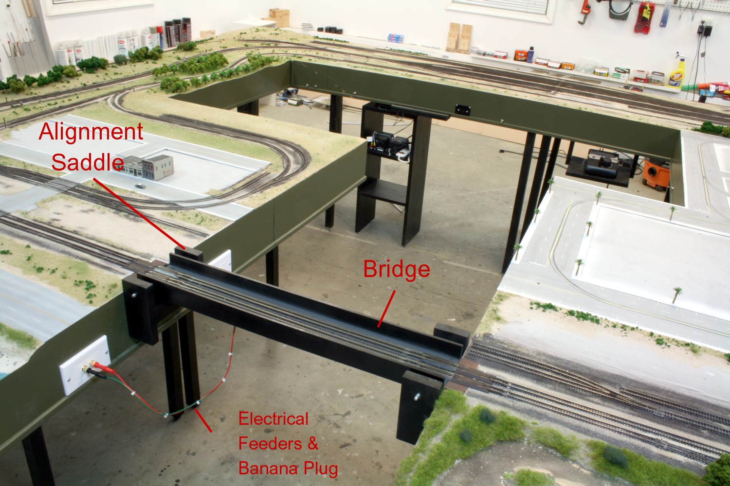
There are three components to the design: the bridge itself, an alignment saddle that holds it in place, and an electrical jumper wire that feeds power to the bridge track.
———————–
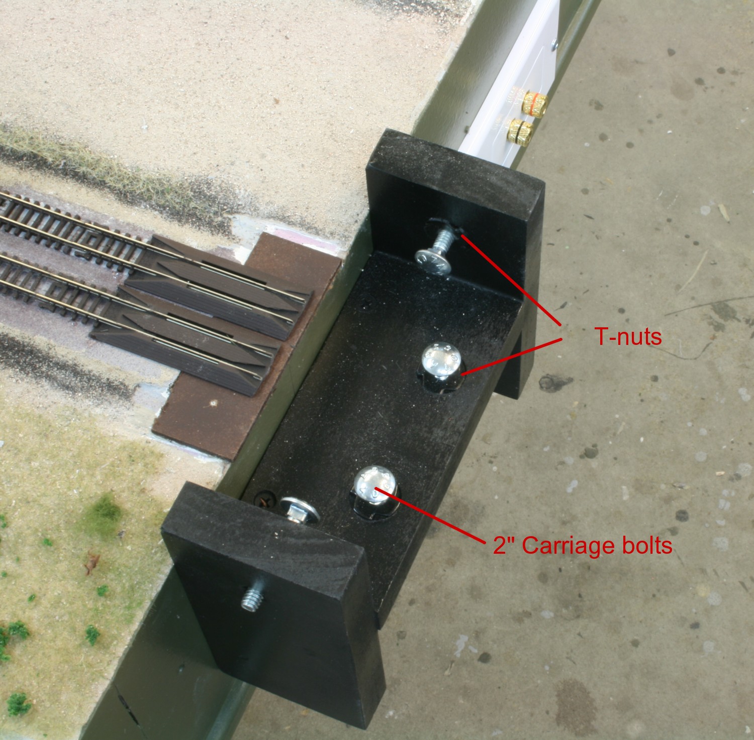
The saddle is a simple box made from 1×3 maple (a harder wood). T-nuts are inset in the bottom and the sides of the saddle and then 2″ carriage bolts are threaded into the t-nuts. A quick spin of the bolts allows infinite adjustment (vertically and horizontally) of the bridge that is seated in it.
—————————–

Here’s the bridge seated in the saddle. I use a masonite pad under the track at the layout joint as this is more robust than cork roadbed. The re-railers are trimmed to fit. Note that the re-railers on the bridge extend out about 1/8″ and rest on the layout masonite pad when the bridge is in place. The box is a simple design of 1/2″ ply with 1/4″ lattice wood for the side rails.
————————
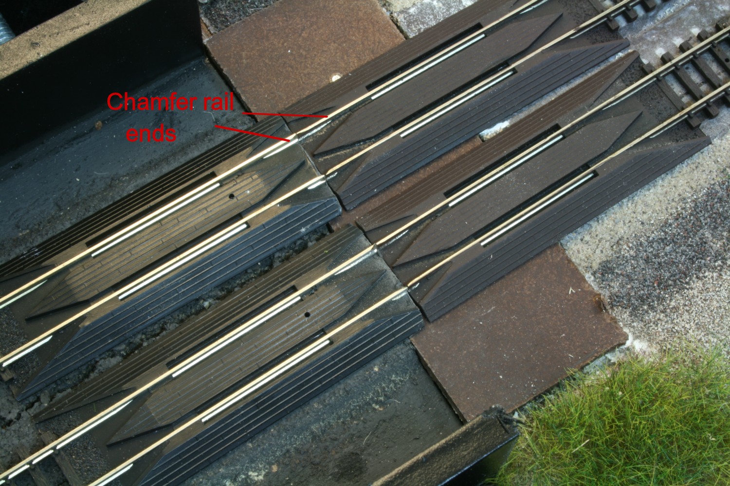
To further minimize the chance of a train “picking the end of the rails” chamfer both sides of the track.
————————-
Removal of the bridge is a simple matter of un-plugging the banana plugs and lifting it out. Also keep in mind that, for most of us, the time spent working on the layout typcially far exceeds the time we actually run trains. Factoring that in, the time we spend interacting with the bridge is limited. Just set it aside until you want to do some train running.